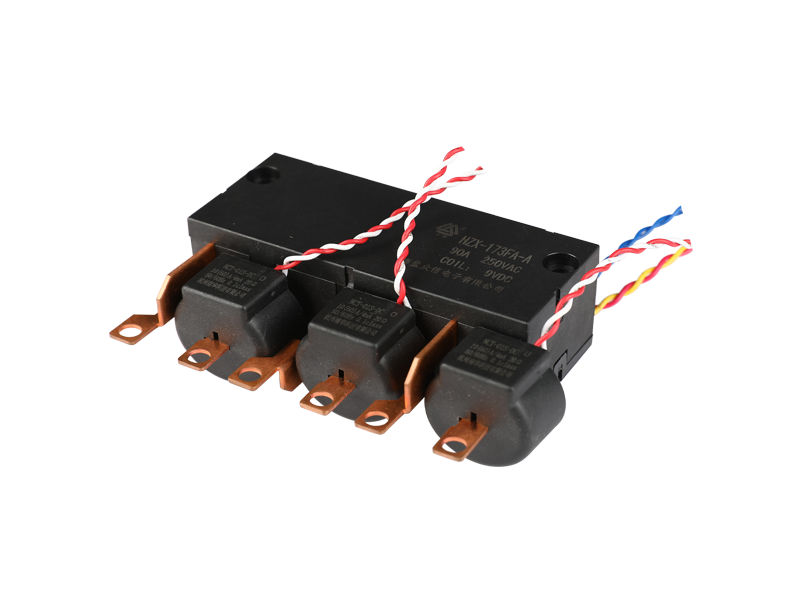
The relay is a commonly used component in the control circuit. It uses the principle of electromagnetic induction to control the connection or disconnection of a certain circuit, and realizes the control of a large current with a small current, thereby reducing the current load of the control switch contact and protecting the switch. Contacts are not ablated.
Relays are widely used in electrical control circuits, such as intermediate relays, time relays, closing relays, tripping relays, etc.
1. The structure of the relay
Electromagnetic relays generally consist of iron cores, coils, armatures, return springs, and contacts. The figure below shows the internal structure diagram of the normally open and normally closed hybrid relay.
Second, the classification of relays
Relays can be divided into normally open relays, normally closed relays, and normally open and normally closed hybrid relays according to the connection and disconnection methods. Several common relays are shown in the figure below.


3. The working principle of the relay
The working principle of the relay is shown in the figure below. When the switch is closed, a certain voltage is applied to both ends of the coil, and a certain current will flow through the coil, thereby generating an electromagnetic effect, and the armature will overcome the pulling force of the return spring to attract the iron core under the action of electromagnetic force. As a result, the movable contact of the armature is attracted to the static contact (normally open contact), and the red light bulb lights up at this time. When the coil is powered off, the electromagnetic suction will disappear, and the armature will return to the original position under the reaction force of the spring, so that the moving contact and the static contact (normally closed contact) will be closed, and the green light bulb will lights up. In this way, it is attracted and released, so as to achieve the purpose of conducting and cutting off in the circuit.
For the "normally open and normally closed" contacts of the relay, it can be distinguished as follows: The static contact that is in the disconnected state when the relay coil is not energized is called "normally open contact"; The static contact in the on state is called "normally closed contact". Relays generally have two circuits, one for the control circuit and the other for the working circuit.
Fourth, the detection of the relay
1. Measuring resistance
Use a multimeter to block and detect the resistance of the relay coil to determine whether there is an open circuit in the coil.
2. Power-on detection
If the resistance meets the requirements, apply the working voltage to the relay coil, and then use a multimeter to check the conduction of the contacts. If it is a normally open contact, after loading the working voltage, the contact should be closed, and the measured resistance is 0; Close the contact, after loading the working voltage, the contact should be disconnected, and the measured resistance is infinite.
According to the terminal number marked in the above figure, check the connection terminals 86 and 85 with the resistance R×100 of the multimeter, it should be connected (with a certain resistance value), and the resistance between the connection terminals 30 and 87 should be infinite (as shown in the figure below); Add 12V voltage between terminals 86 and 85, use a multimeter to measure terminals 30 and 87, and it should be connected. If the detection result is not consistent with the above, it means that the relay is damaged.


